Over 10 years we help companies reach their financial and branding goals. Engitech is a values-driven technology agency dedicated.

Gallery

Contacts

411 University St, Seattle, USA

+1 -800-456-478-23

Case Studies Telecommunications
PAU Card Image

SLC-96 Reverse Engineering

The 'Slick-96' appeared in utility boxes all over

Reverse engineering, the art of taking things apart to figure out how they work, is one of MTSI’s specialties. From the beginning, we’ve completed reverse engineering projects worth millions of dollars for industries encompassing nuclear energy, defense, telecommunications, software, video games, and healthcare systems.

Due to the regulation of the telephone industry, a client successfully reverse engineered cards originally produced by Western Electric for the Subscriber Loop Carrier (SLC) 96 — a digital loop telephone system that could carry up to 96 subscriber channels using T1 digital lines. However, several cards were extremely difficult to reverse engineer. 

These cards had a lot of full-custom ICs — including a microprocessor, EPROM memory, and a pair of gate arrays with more than 10,000 gates each.

MTSI had already been successful in reverse engineering software. In one case, a complex voice compression algorithm was legally reverse engineered, and the resulting differential adaptive, lossless DAPCM voice compression equation was short enough to print on a t-shirt.

Central office terminal equipment. AT&T Bell Laboratories photo

SLC-96

Western Electric developed the SLC 96 (pronounced “Slick 96”) to bring digital capability to local loop networks (.pdf) — the physical link or circuit that connects from the demarcation point of the customer to the edge of the service provider’s network. In essence, it was technology to provide faster telephone service to people living in rural areas with a T1-type line while expanding capacity in large metropolitan cities.

The first digital loop carrier system was introduced in 1971. There were several iterative generations during the next few years, including the D4 which was introduced in 1976, and then the SLC 96 in 1979, which shared a similar physical format and technology to the D4. The SLC 96 received a fiber-optics upgrade in 1982 and were installed in vast numbers across the United States.

The system used two channel banks: one located in a central office to interface to a local switching machine, and the other located remotely in the vicinity of a group of subscribers. Communication was by fiber or T-1 line. The SLC 96 provided telephone service, coin service, special services, and data services.

The design was patterned after the D4 channel bank, and many of the D4 carrier’s channels units worked in the SLC 96. The machine’s time assignment board took an alternate sequence of channels to place the 8-bit PCM codeword from channel slots into time slots. From the first channel slot into the first time slot. Then the word from the seventh channel slot into the second time slot. And so on.

The transmit encoding logic in card could also select an 8-bit encoded PAM signal or an 8-bit digital data signal inserted into any time slot of a PCM bit stream. The doubled the channel capacity of a 24-channel T1 line.

Additional requirements existed. Four different cards were required, and it all needed to withstand an extreme temperature range, operate with reduced power, hjave high reliability, and with a low cost of manufacturing. There was a good reason for this — these telephone systems needed to hold up in every conceivable location.

TAU-Card-prototype-Back-background-removed Image
TAU-Card-prototype-Back-background-removed
SLC 96 boards.
FlowChart Image
Sequence to set up dc bypass path to customer's drop. AT&T Bell Laboratories illustration
Channel Slots Image
Sequence of the time assignment unit. AT&T Bell Laboratories illustration

MAC-8

Solution

MTSI first developed a disassembler for the MAC-8 processor code. The MAC-8, better known today as the BELLMAC-8, is an 8-bit microprocessor designed by Bell Labs, which began production — in CMOS form — at Western Electric in 1977, when it was known as WE212. The MAC-8 was only used in AT&T products. 

It was an unusual chip as the registers were in RAM, but it had very fast interrupt response time by just changing a pointer to the registers.
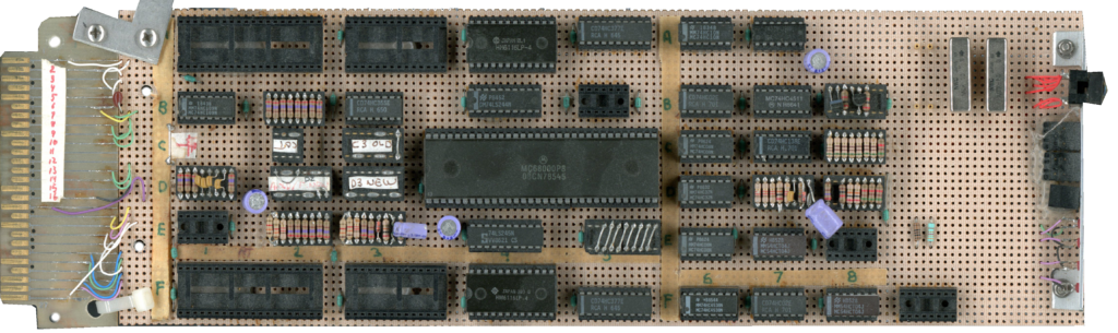
One of the first steps was to translate 6,000 bytes of code into the target 68000 computer language, and emulate the MAC-8 register stack with a 68000 register. Timing was recovered from the MAC-8 manual and the translation process was able to calculate that all emulated op codes were executed as fast or faster than the original code.

During this development, we also found a design flaw in the Hitachi 68000 microprocessor and reported it to the manufacturer, which had to perform mask changes to eliminate the problem. The problem was in the Move Multiple Long instruction.

A sequence such as:

movem.l R1-R5,A4, -@sp

was used to store registers. The opposite instruction was used to pop them back. We then discovered another design flaw — a mask flaw which caused the registers to be restored in the wrong order. Hitachi field engineer Wayne Weirich arrived, confirmed the flaw, and reported it back to Hitachi. The next day, we received a ECN from Hitachi reporting that it had been fixed. We learned that one mask existed and had the flaw, and after a certain date, half the parts had the flaw — then after our report, no chips had the flaw.

The hardware was examined using logic analyzers, a computer-aided engineering workstation, and other tools. Simulated circuits were tested against the known good circuits and modifications made. Seventeen full-custom IC’s were reverse engineered in this way.

Reliance Comm/Tec Ad

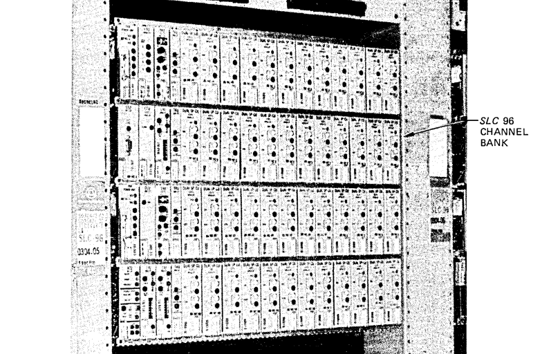
We also needed to incorporate worst-case timing changes into the design, so we developed an SLC 96 simulator controlled by a PC. 

This reduced the need for the expensive and often unavailable pair of SLC 96 systems. 

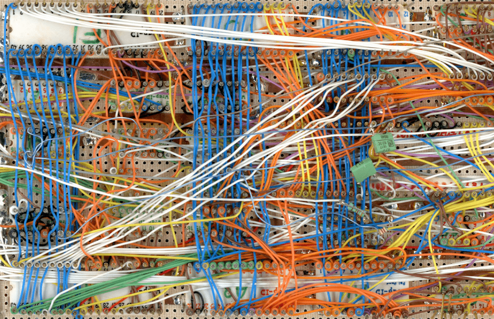
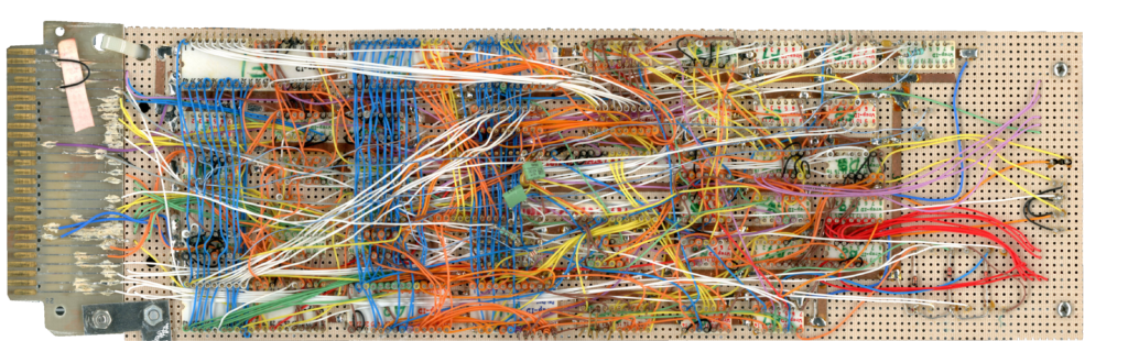
Lastly, MTSI developed a gate array emulator and prototyped it with wire-wrap technology. At which point four emulators were built and tested. 

The design was then extensively simulated and a gate array produced that matched the required functions.

Altogether, 23 emulators were built and tested individually and together. By using PLD technology, power was reduced, the need for full-custom circuit was eliminated, and the design was rapidly developed and tested.

All four cards entered volume production. The gate array was found to be 100 percent correct after the first pass. 

All of the projects were under budget and on time.