Testing the Z80 Chip With a 1970s Beauty
The Fairchild Sentry 610 was optimized for engineers
by FRED BECKHUSEN
If you used a Z80 chip back in the 1980s, it almost certainly passed through a single room and its Fairchild Sentry 610 test system. Mostek had grown into the one’s top producer of DRAM, and every Z80 microprocessor — including Zilog-branded ones — went through tests there.
Mostek also tested Fairchild F-8 CPU chips and exotic parts such as the Magnavox “Star” T.V. tuner chips. The system was general purpose enough, we could test RAMs, ROMs and calculators — though we made our own custom testers for these. The room did most of the heavy lifting on all of the early CPU chips. Mostek also had a second-source license for many popular CPU chips — the Farichild F-8 series, the Z80, the Intel 8088/6, and the Motorola 68000 family.
Several MTSI engineers began their careers at Mostek which invented the multiplexed DRAM, too. But back in 1971, Mostek’s engineers were introduced to the Sentry 610. Fairchild Systems had just introduced the first computer-controlled, modularized, expandable test system product line in the the Sentry series. These third-generation systems were designed to test complex MSI/ LSI integrated circuits, electronic subsystems, and systems.
The machine was a beauty.

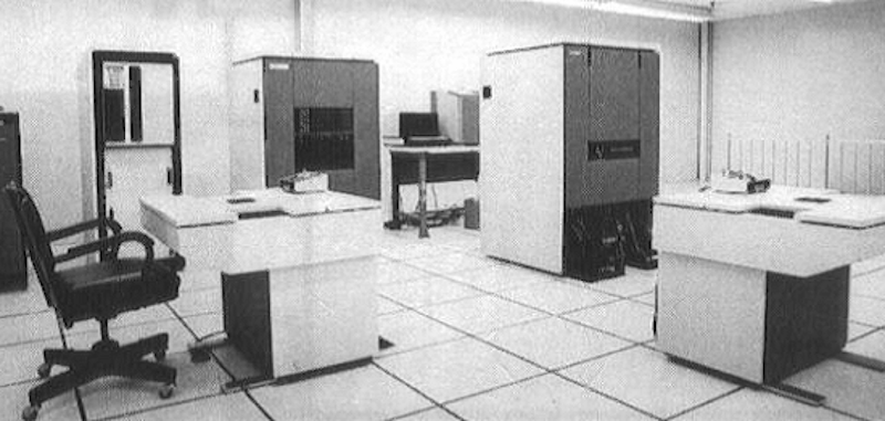
From clockwise from the upper left, the system comprised a disk drive, a 9-track tape, the Fairchild 24-bit CPU, a terminal and printer, the Sentry 610 Tester, and a pair of 64-pin test heads. The door to this temperature and humidity-controlled room is on the right, in the back of this photograph, down the ramp to the right.
The disk drive was a head-per-track unit, with a large platter rotating on its side. It was 26 inches in diameter and stored 75,000 bits. This particular disk developed flakies in 1974, so I was elected to drape it with plastic, crawl under it, and spend a shift carefully wiping the surface with alcohol. To my surprise, it worked. The surface looked like raw steel instead of the oxide that I expected.
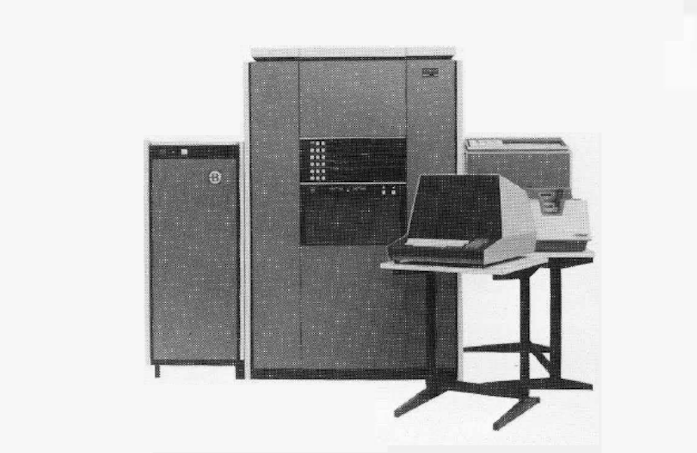
The CPU was a Sentry 400-series CPU running “Factor,” Fairchild’s test language. The machine was 24-bits wide at about 250 Khz. There were two boxes of cards, about 12″ X 18″, and 12 boards with 2-bit slices per board. You could access it by pulling the black latch on the left side, and swinging open the door. On the front of the CPU was a LED bank behind plexiglass to make Blinkenlights. I still have the test handbook for it.
This CPU had a “short” and “long” bus mapped to the various peripherals. One night it failed to boot, which would cost a few thousand dollars an hour. I assigned a technician in training to fix it. An hour or so later he found it, but did not know what to do next. He toggled the switches to go to the short data bus, and after many flicks of the switch and looking through a file cabinet of documentation, he proved to me he was able to write the necessary data to access the disk via the long data bus and read back the disk register.
Sure enough, there was a bit set, which the documents said was the “disk online” bit, and it was off.
“Oh,” I said. I turned around, and the “Online” switch was flipped downward on the disk. “Click.” It was a great learning lesson in depth of how the CPU worked, for him and me both.
“Optimized for engineering, sophisticated production needs, QA and test center operations, the Sentry 610 is the most versatile analytical tester available for engineering and production. It can perform the widest range of tests for the broadest range of components. At user option, the Sentry 610 can perform high-speed MaS/LSI, PCB, and bipolar tests simultaneously. It offers complete testing at the wafer level and through automatic handlers at full-rated device speeds up to 10 MHz. The wide choice of peripherals gives the Sentry 610 system massive data handling capacity to manipulate, analyze, compute and generate reports on test procedures in analyzing MaS/LSI."
A Profile of Fairchild Systems Technologies, 1975
A full-rated device speed of 10 Mhz was quite fast for this era. The Sentry 610 was based on an 11 Mhz clock and a wild ECL divide-by-11 circuit made of NOR gates and flip-flops which I had to troubleshoot to fix a Magnavox TV tuner test.
The tester had removable panels and two doors that could swing open. Each door held three banks of cards of TTL and ECL logic, with a five-foot-tall, wire-wrapped backplane. I once tried to count the ICs in the tester and came up with a number — around 60,000 chips. The center panel was filled with large — and very heavy — rack mount power supplies. At the bottom, in the black area, were three-phase twist-n-lock 220V power connectors, a bank of 110V AC utility outlets, and cables running to the two test heads. The black panel running horizontally had some test BNCs no one ever used, and a key to power it off and on.
We had to be careful about those AC utility jacks. The tester ground was at -11 volts at several hundred amps. If you clipped a scope to a ground, it would happily melt the insulation off the scope probe until it stunk up the room and pooled on the floor. We had to use a three-prong adapter with the ground cut off.
The tester could DMA test patterns from the disk to the pins of the DUT at full speed, change power supply voltages at megahertz rates, and via microcode running out of ECL RAM, call test subroutines in hardware at the full clock rate. Each test vector looked like a binary 101011..001, 64 bits long, and each bit set an output high or low, or was an expected response.
These bits basically were wired to the test pins. Someone wrote a Z80 cross compiler that made “Set F 10101010101……100101” statements from assembly language, so we could test actual code on the Z80 at full speed. It was exotic tech for us. We could only compare it to the assembly language PDP-11 testers we typically made. Mostek made all their own custom testers except for these.

The test heads had a circular array of pin electronics (PE) cards. PE cards had a lot of analog circuits for testing the device under test (DUT). This particular machine had a 50-pin capacity.
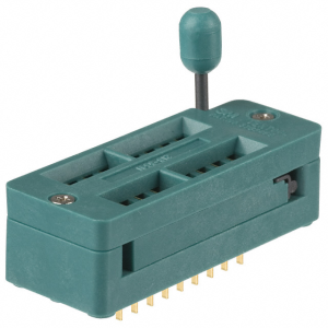
The DUT was plugged into a “top hat” that had a ZIP DIP socket which in turn was attached to the performance board that had the loads and any special circuits for that part, which in turn plugged directly onto the circular array of PE cards.
These IC-specific parts could be changed quickly, a new tape loaded by 9-track, and a new test set up in a few minutes.
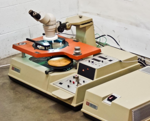
The test heads were built to hold the very heavy Electroglas wafer testers, too.

Fred Beckhusen is founder and CEO of Micro Technology Services, Inc.


